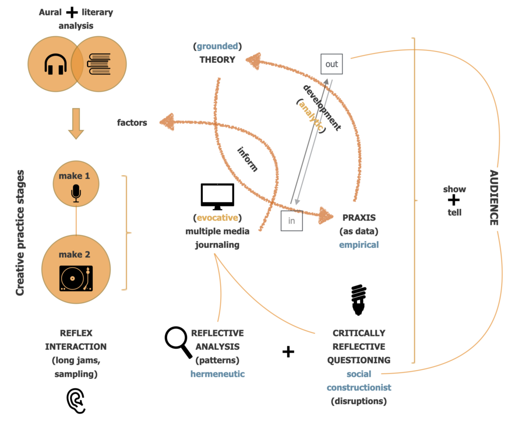
A schematic representation of actioned phases in the research design, mapped against fitting methodological paradigms and (Cunliffe’s triangle of) sense-making stages.
Figure I.2
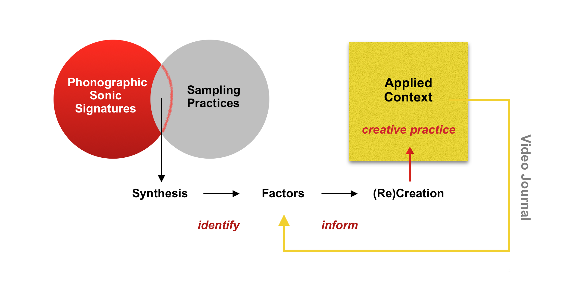
First phase of the research design depicting the deployment of literature on phonographic signatures and sampling practices to identify key sonic factors influencing sample selection. These factors inform the creation of original source audio in the following, applied creative-practice phase.
Figure I.3
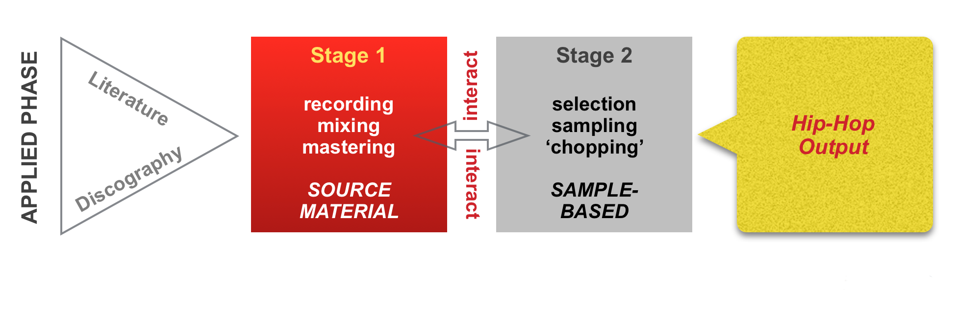
Second—applied—phase of the research design comprising two practice-based stages. The primary stage involves the recording, mixing, and mastering of original content, informed by historical and technical detail derived from the first phase. The second stage involves the selection of samples from the recordings/masters made in stage one, facilitating the beat-making process that leads to the associated album.
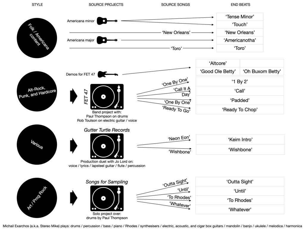
Figure/multi-table 0.1
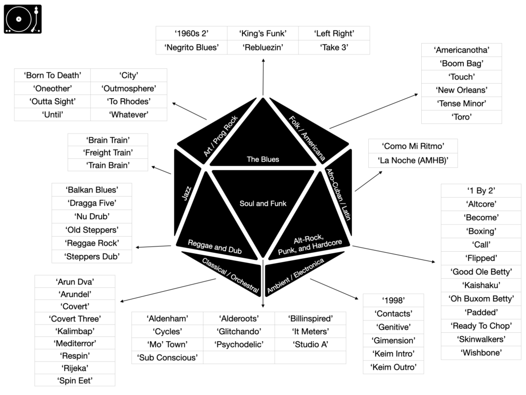
A mapping of the genres/styles of source audio produced to facilitate the beat-making process, mapped against tables of the final sample-based productions comprising the accompanying album.
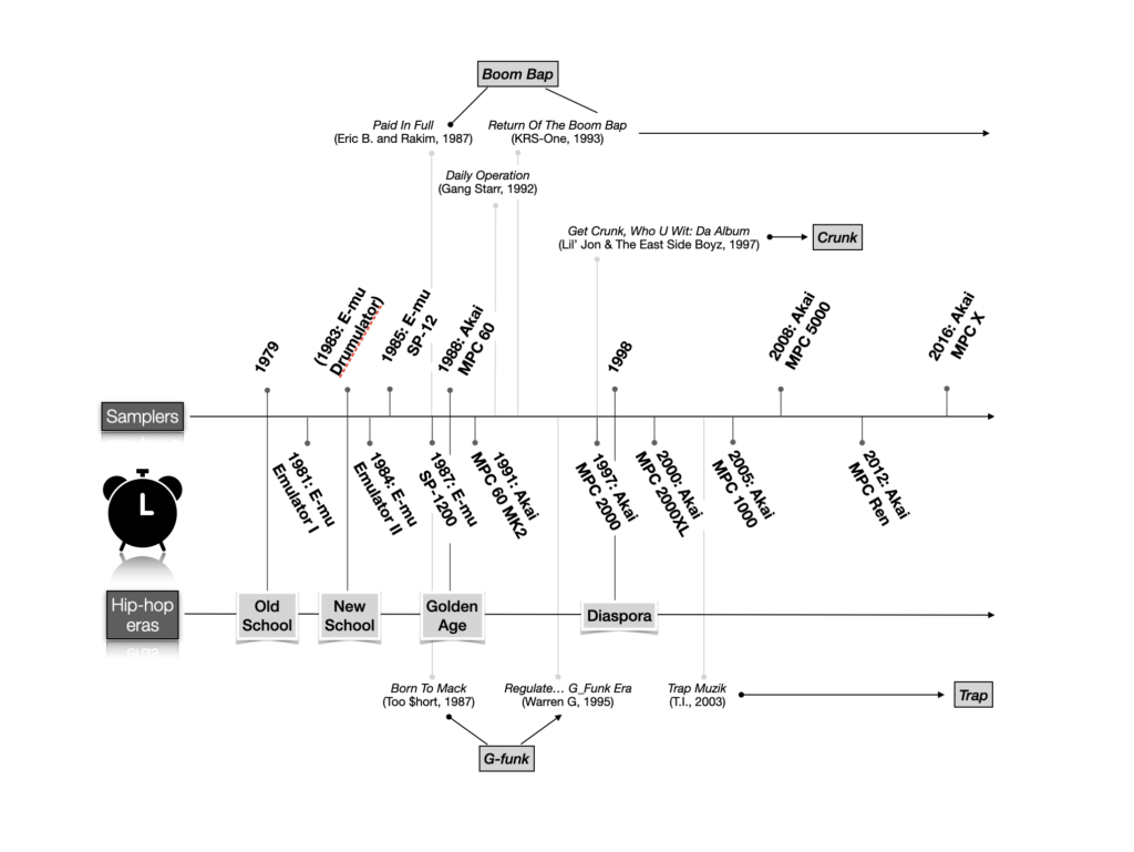
Figure 2.1
Timeline mapping hip-hop eras against E-mu and Akai products, with examples of seminal releases characteristic of rap subgenres.
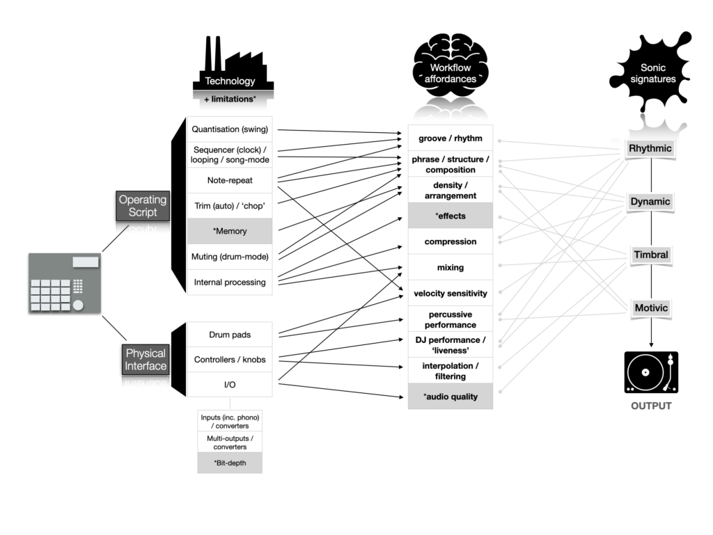
Figure 2.2
A schematic representation of technical characteristics of the MPC range mapped against workflow affordances and sonic signature categorisations.
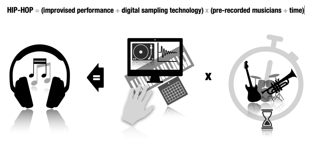
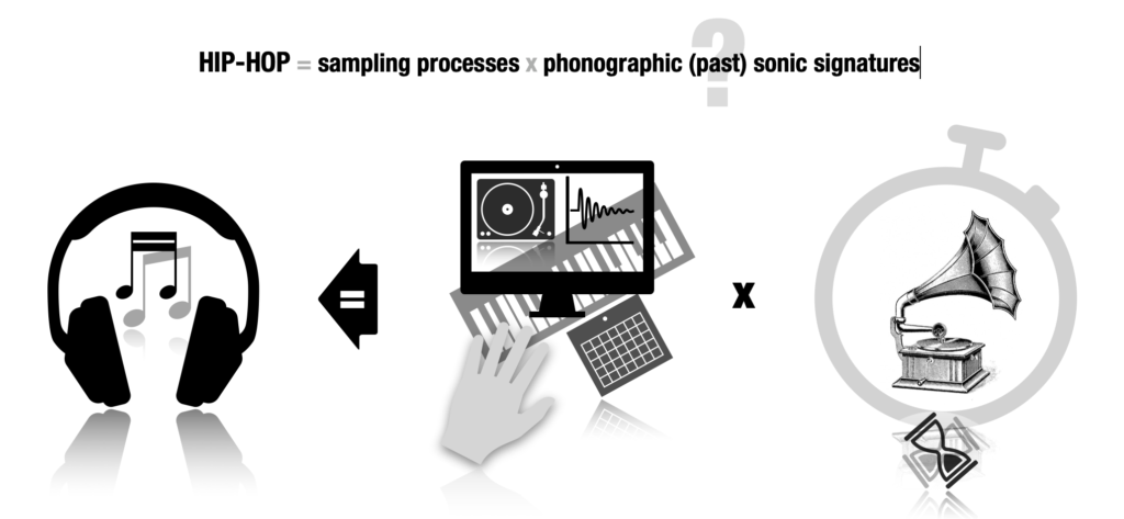
Figure 3.1
A schematic representation of the ‘hip-hop time machine’ equation.
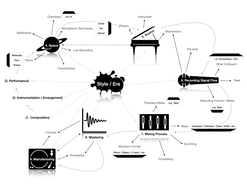
Figure 3.2
A schematic representation of essential phonographic sonic characteristics and related variables.
Figure 3.3
A schematic representation of source outputs correlated to end beats.
Figure 3.4
A schematic representation of the interaction between sampling processes and (past) phonographic sonic signatures, defining the hip-hop aesthetic.
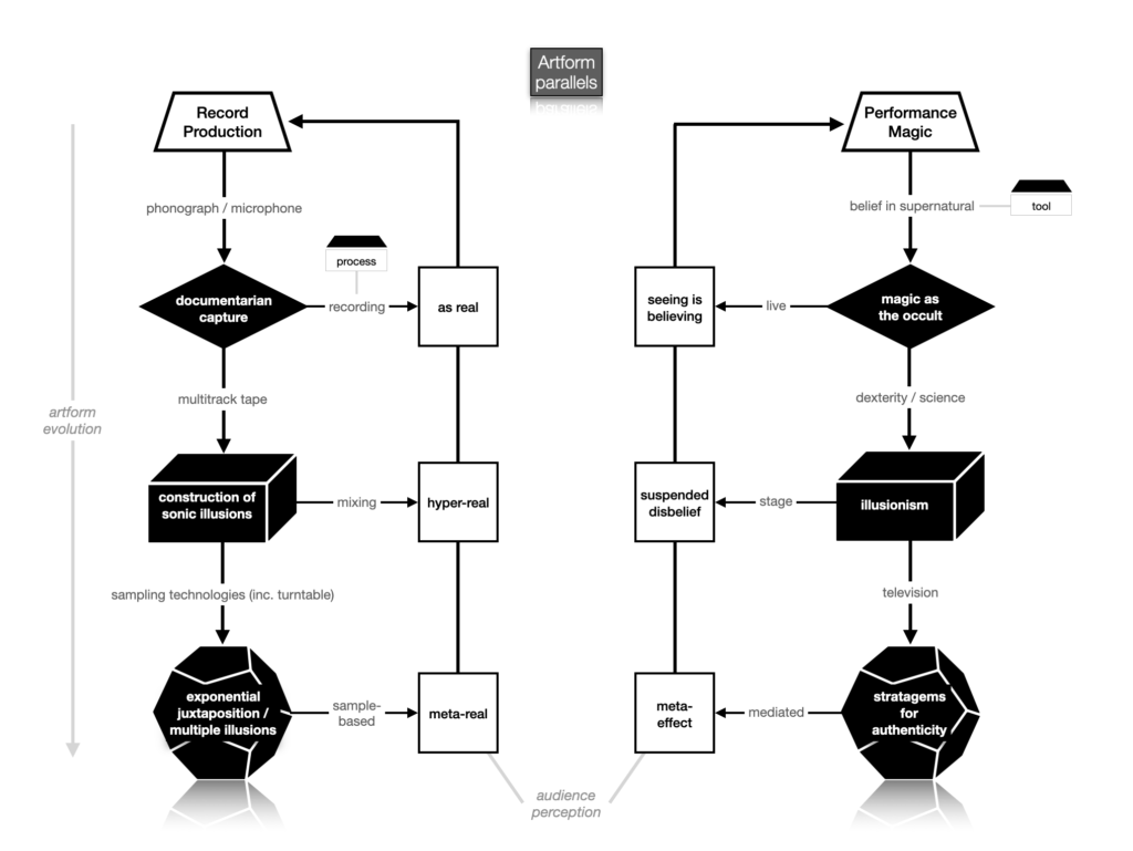
Figure 4.1
A schematic representation of the parallel evolutionary streams for record production and performance magic.
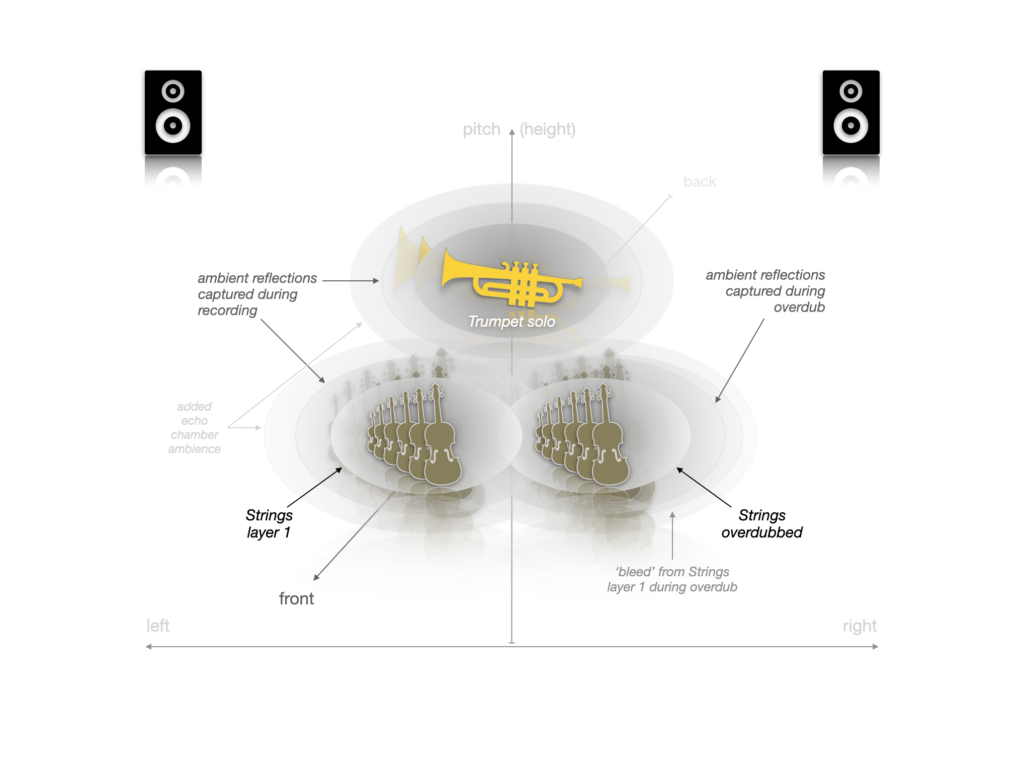
Figure 4.2a
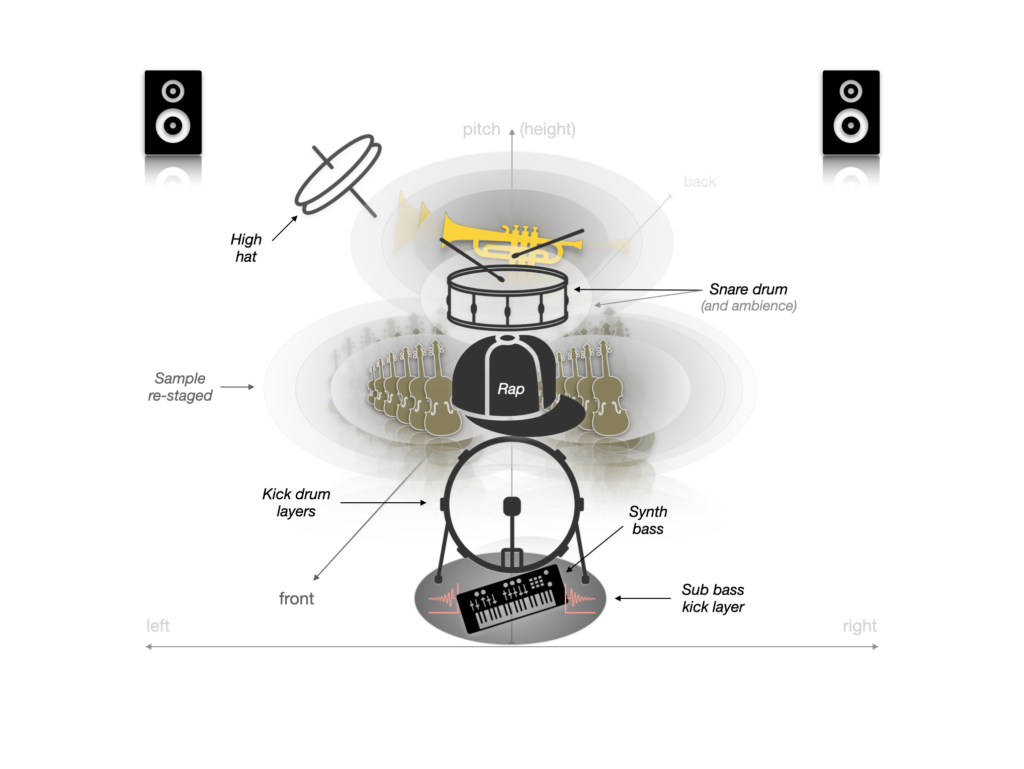
A schematic representation of the sonic ‘space’ occupied by the sample from ‘A Theme For L.A.’s Team’.
Figure 4.2b
A schematic representation of the exponential staging illusions on track ‘Musika’.
Figure 4.3
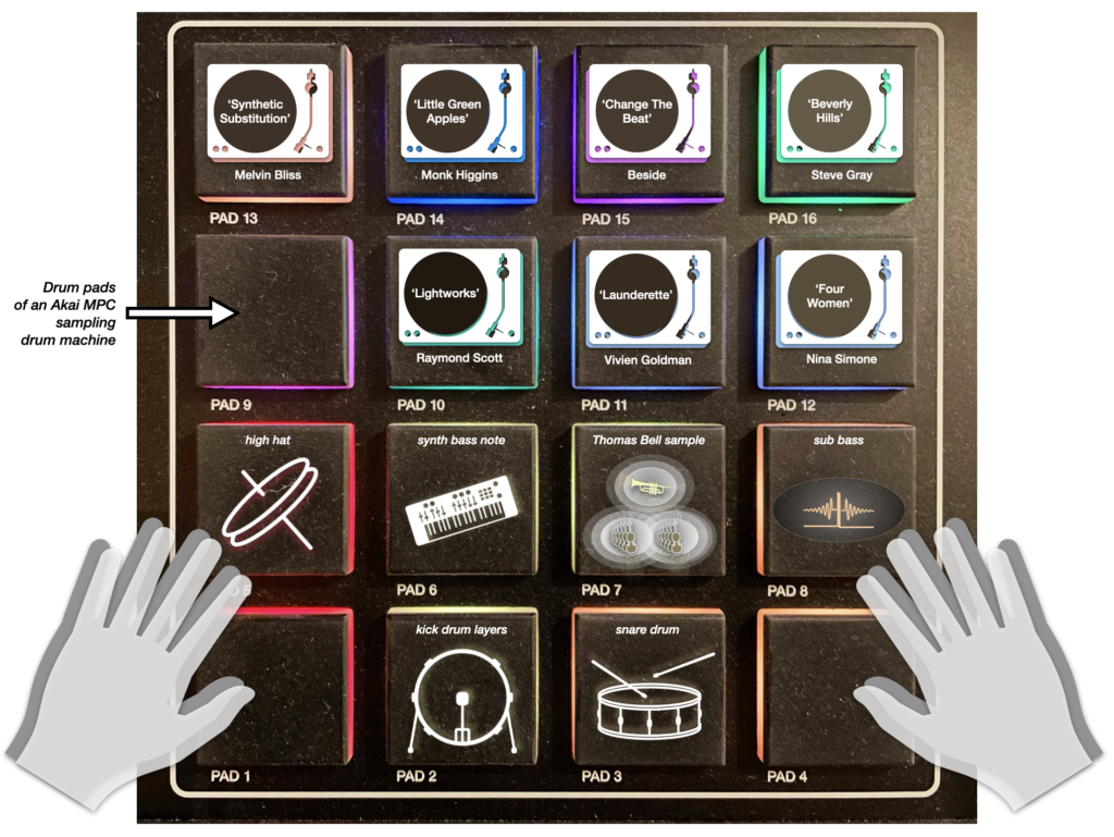
A schematic representation of the sampled examples discussed in chapter 4, on the drum pads of an Akai MPC sampling drum machine.
Figure 5.1
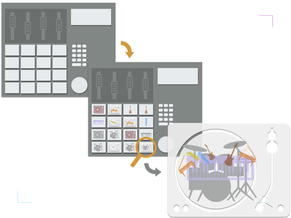
A schematic representation of a digital sampler (with mixing functionality), enabling the manipulation of multiple record segments, which in turn contain productionsof live performances.
Figures 5.2a & 5.2b
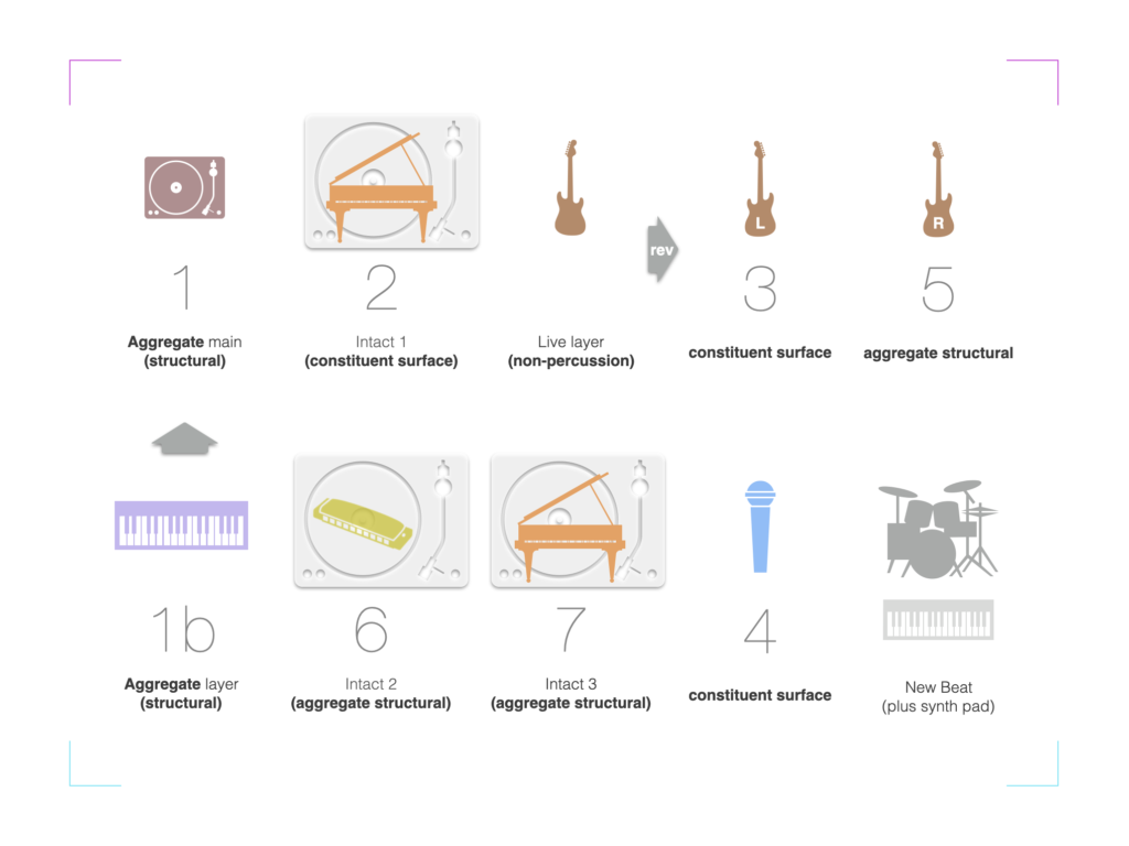
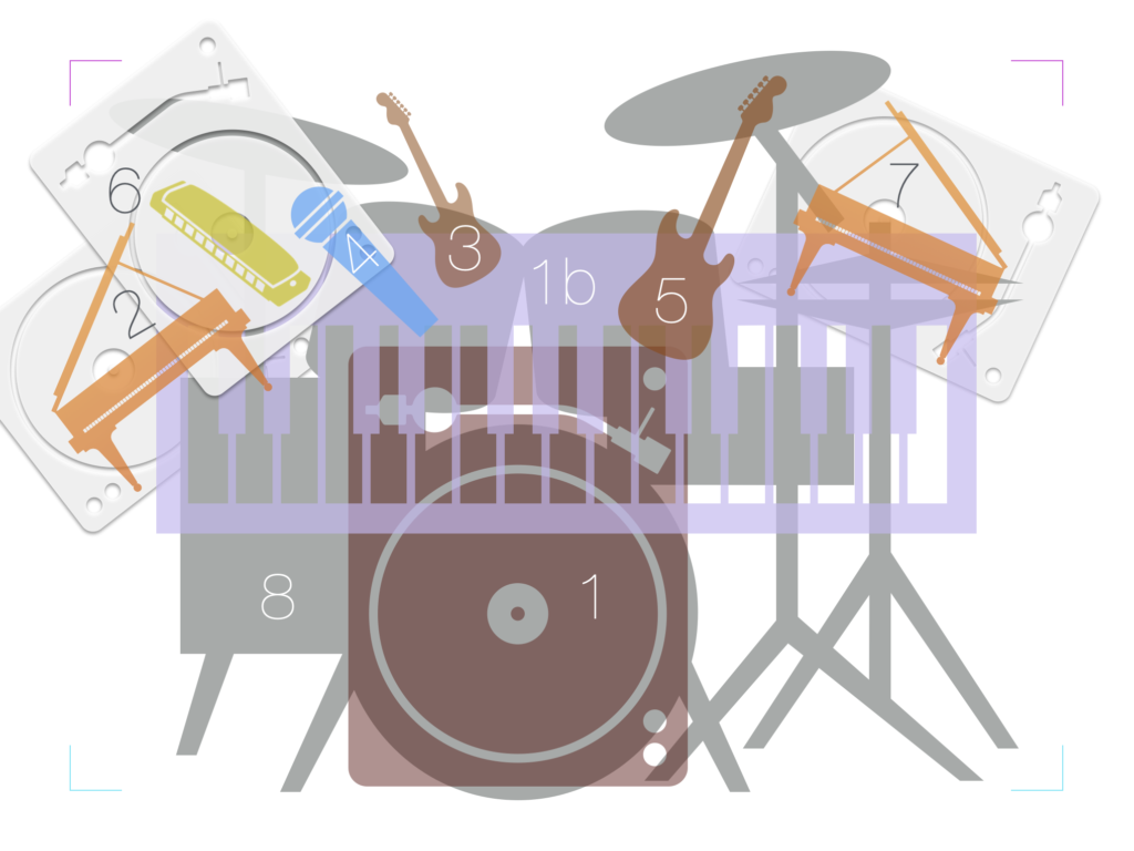
A schematic representation of the individual sample layers and their staging in the final sample-based production, album track ‘Call’ (the numbering of the sample representations corresponds to table 5.1 in chapter 5). Note that samples 2, 6, and 7 are represented by a turntable framing the instrument most accentuated by filtering, indicating intact structures (mini records within the record).
Figures 6.1a & 6.1b
(a) A schematic representation of the perceived staging of the chorus in Melba Moore’s ‘The Flesh Failures (Let The Sunshine In)’ and (b) its reshaping in Kanye West’s production of Mos Def’s ‘Sunshine’ (the new beat elements enter at the end of the chorus, while a different segment from the original is used for the verses).
Figure 6.2
A collage of photographs from the recording sessions responsible for the production of the constructed multitrack ‘sample’ used in album track ‘Reggae Rock’.
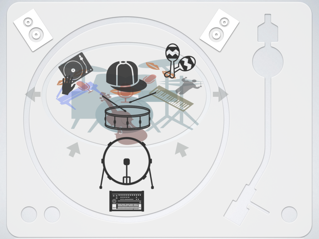
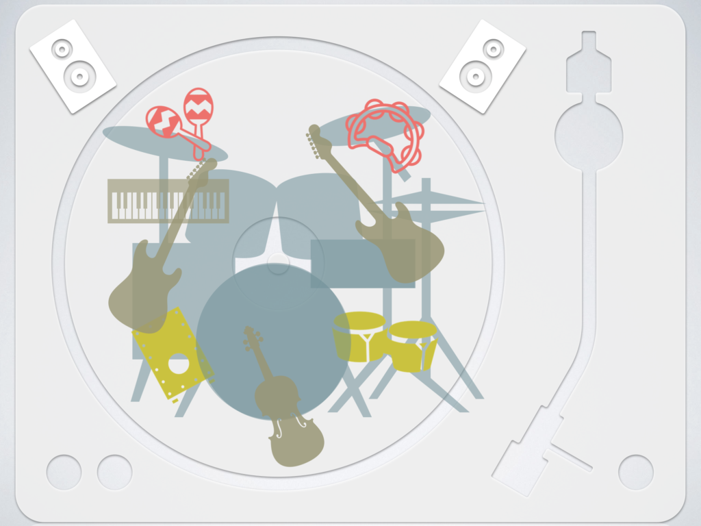
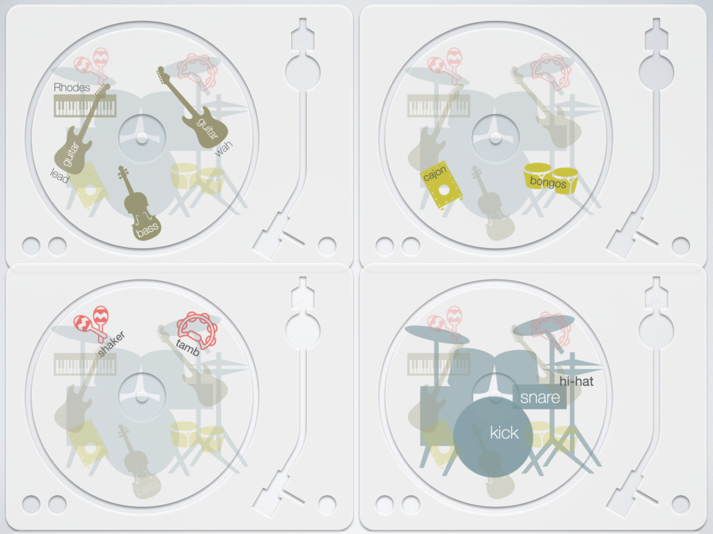
Figures 6.3a, 6.3b & 6.3c
(a) A schematic representation of the staging of the multitrack used as the foundation for section A of ‘Reggae Rock’.(b) A schematic representation of the four component layers extracted from different sections of the source multitrack: a non-percussion layer that includes Rhodes piano, bass, and lead and rhythm guitar (top left); and three percussion-only groupings of cajon-and-bongos (top right), shaker-and-tambourine (bottom left), and drums (bottom right). Note that under each layer’s representation there are opacities overlaid of the missing instruments’ positions within the implied, original mix architecture.(c) A schematic representation of the resulting aggregate structure, plus the new beat additions: the sepia colour added represents the vinyl crackle that has been layered over the aggregate structure; the cajon-and-bongos percussion-only layer has been shifted to the right in terms of lateral imaging, while the arrow pointing down from the new snare and toward the sampled drums’ snare represents side-chain compression applied upon the drum layer.